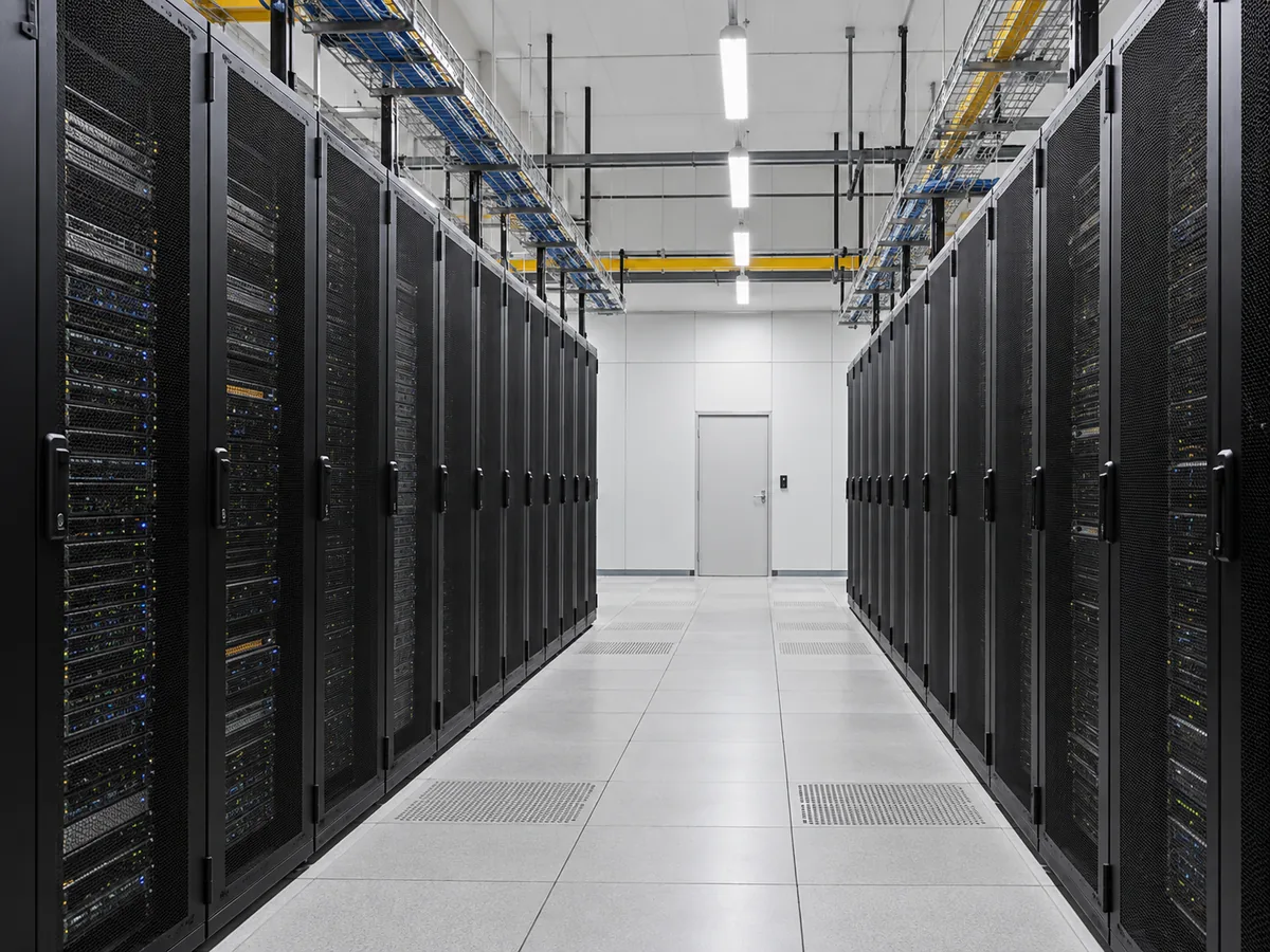
Data Halls
Room boundaries around rack layouts, supply and return paths, and access routes in larger equipment spaces.

Modular wall and ceiling panels, doors and coordinated enclosure interfaces for data halls, server rooms and data center retrofit projects.
DATA CENTERS / ENCLOSURE & INTERFACES
Plan data center wall panels and modular enclosures around the equipment, cooling layout and contamination-control requirements. AILV manufactures wall and ceiling panels, with doors, windows and openings coordinated for the agreed project package.
From a server-room partition to an AI data hall, define the room boundary and its interfaces early. Equipment requirements guide the environmental target; drawings turn that target into a coordinated enclosure.
FIND YOUR APPLICATION
Explore six common settings. Each needs a defined layout, operating brief and supply boundary.
Room boundaries around rack layouts, supply and return paths, and access routes in larger equipment spaces.
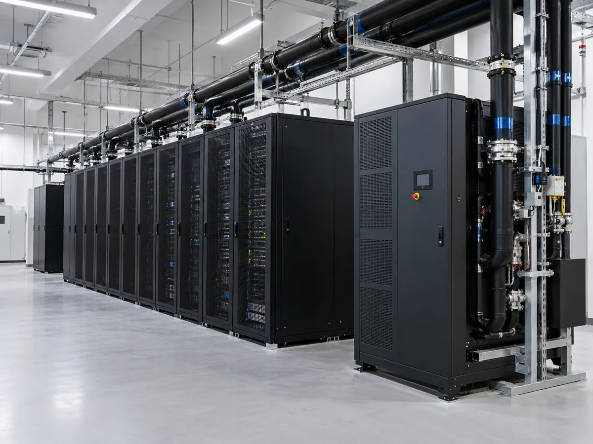
Enclosures coordinated with high-density racks, cooling distribution units, pipe routes and continuing air-cooling needs.
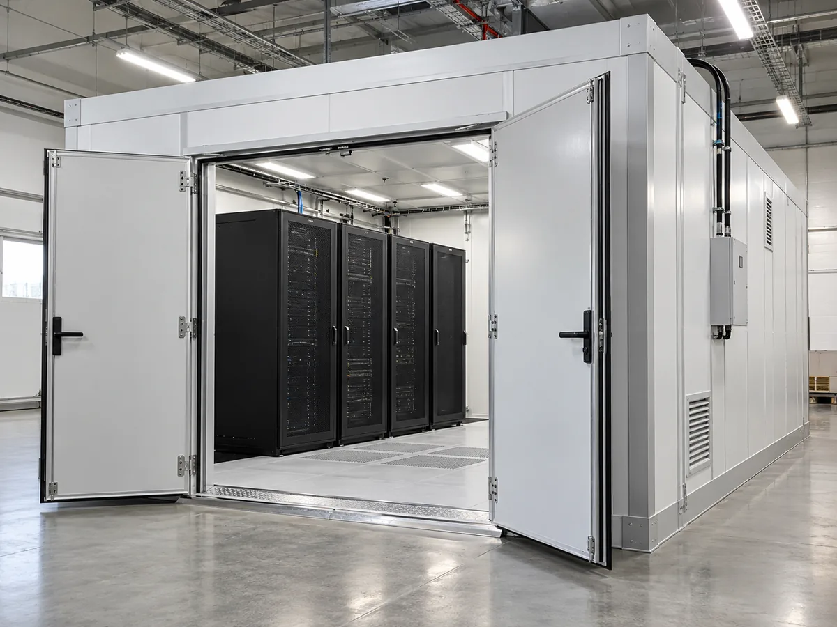
Compact panel packages coordinated around transport constraints, module dimensions, equipment entry and service access.
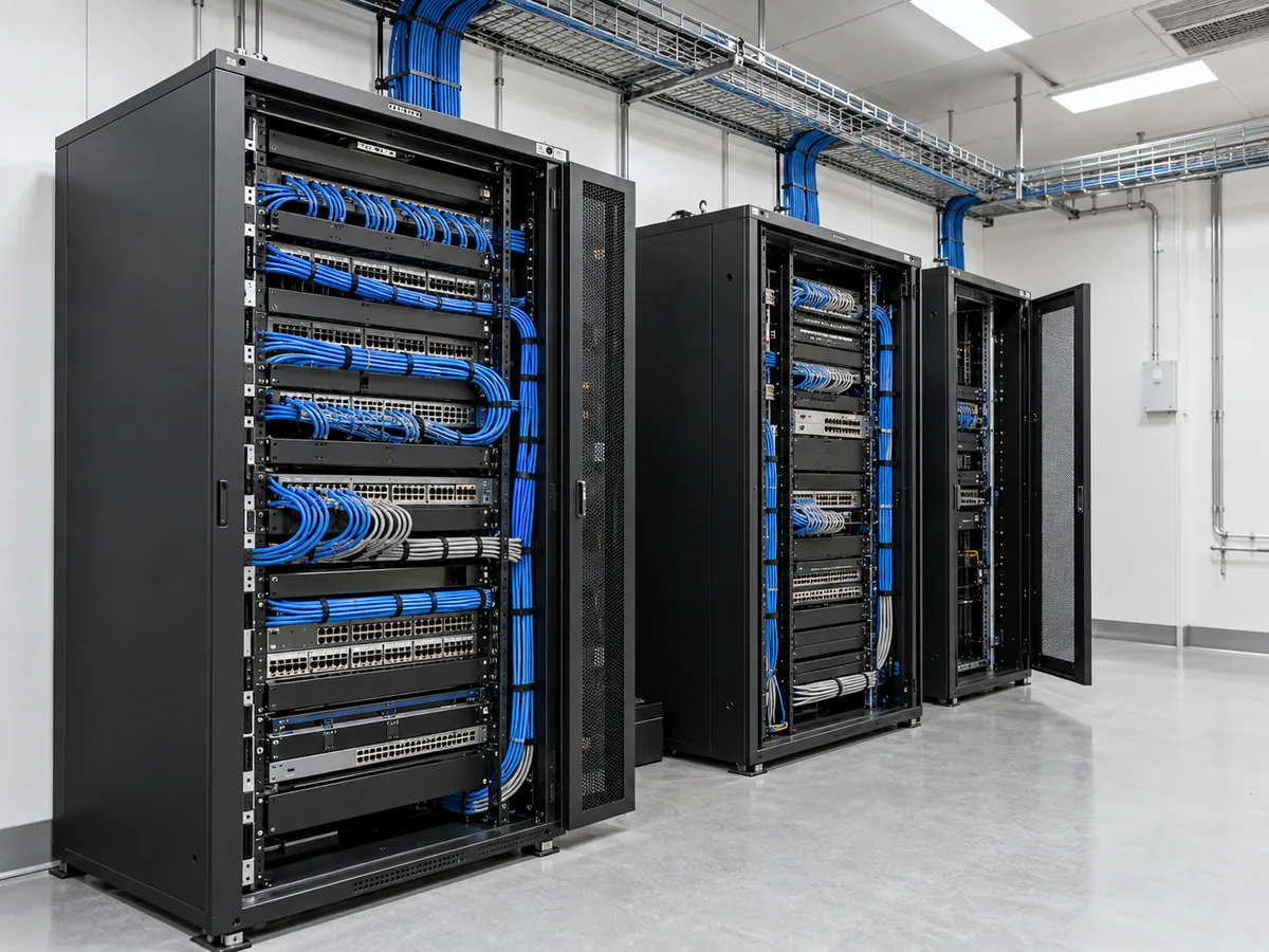
Partitions, doors and vision panels for smaller IT rooms, network equipment areas and local infrastructure.
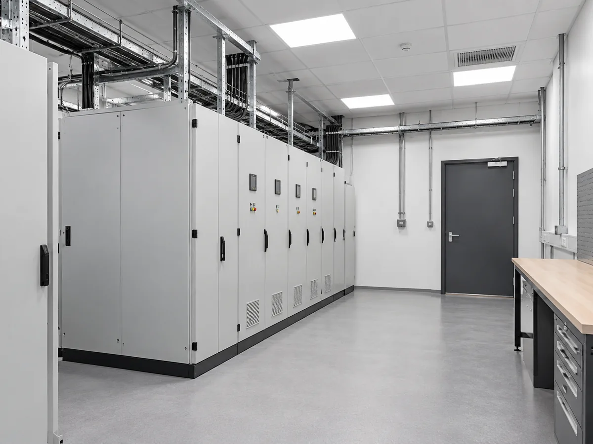
Room separation for staging, unpacking, maintenance and controlled entry into agreed equipment areas.
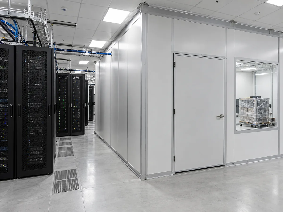
Staged enclosure installation and temporary separation planned around operating equipment and owner access procedures.
DEFINE THE REQUIREMENTS
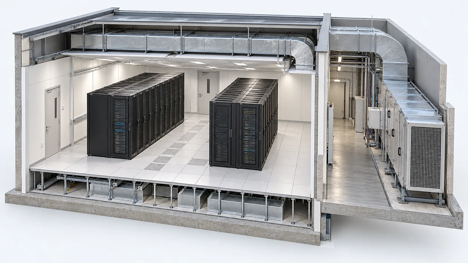
Match enclosure boundaries and openings to the cooling design. Review hot-air recirculation, cold-air bypass and service penetrations.
Plan clean delivery, protected storage, sealed interfaces and site cleaning around the agreed equipment contamination requirements.
Identify relevant outside-air and process risks. The mechanical specialist selects assessment and treatment measures where required.
Review material handling and electrostatic-control needs against equipment and operating procedures, including the complete floor and enclosure system.
Confirm door clear openings, rack and equipment movement, replaceable components and access to filters, pipework and overhead services.
Coordinate partitions and openings with the fire strategy, service penetrations, detection, suppression and required product documentation.
THREE SYSTEMS, ONE COORDINATED BRIEF
Cooling, contamination control and the enclosure solve different problems. Review them together so a filter, opening or partition does not compromise the intended air path.
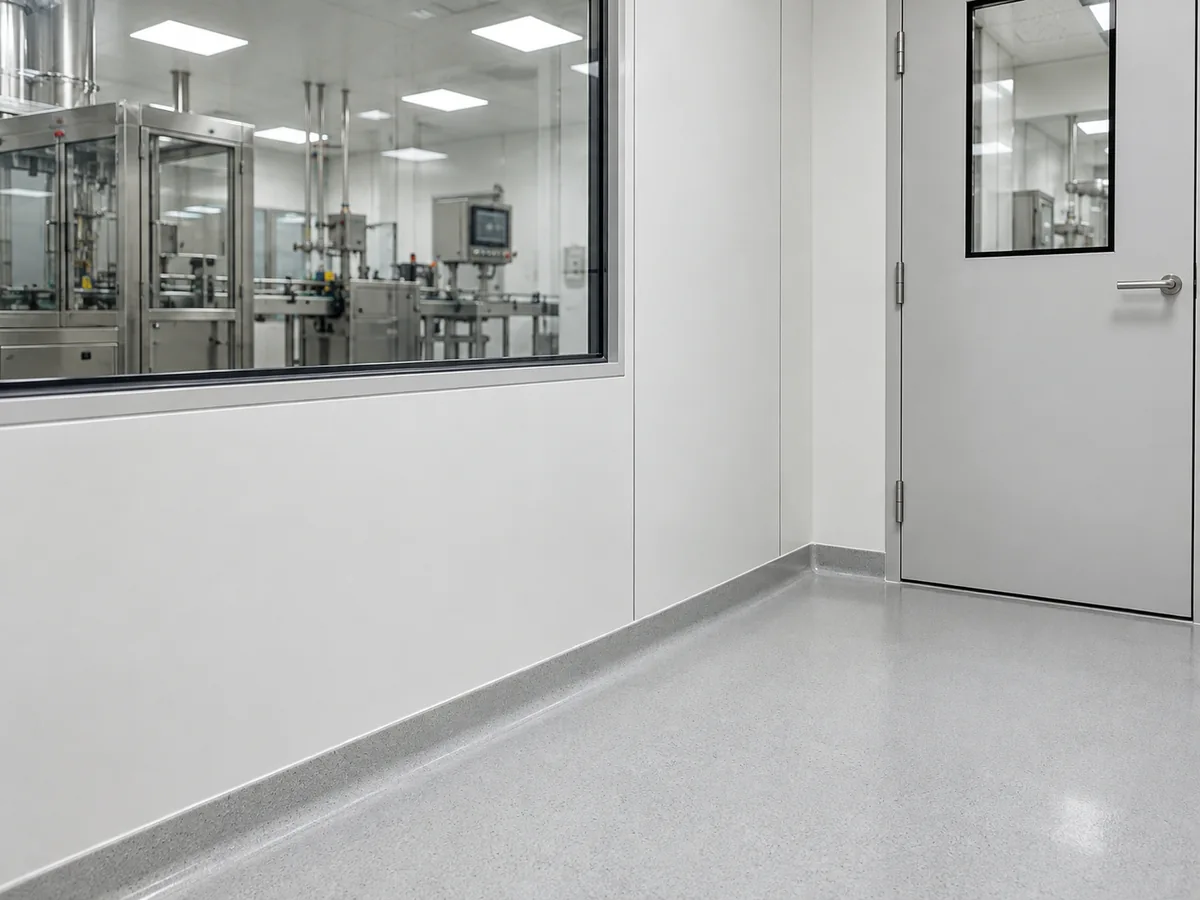
Rack inlet conditions, cooling capacity and supply/return routes guide the air-management design. Aisle containment limits unwanted mixing; it does not assign a cleanliness class.
Identify particles, conductive dust and relevant gaseous contaminants. The equipment documents and site assessment guide filtration and monitoring.
Panel joints, access doors, floor junctions and service penetrations complete the enclosure. Material and personnel routes influence how contamination enters.
Positive pressure can reduce ingress through leaks when supplied air is appropriately treated. It is not a substitute for filtration, sealing or the fire and cooling strategy.
Engineering reference: U.S. Department of Energy data center design guide.
MATCH THE CONTROL TO THE SPACE
Document each room’s use and its relationship to operating IT equipment. A support area does not automatically inherit the environmental target of the server hall.
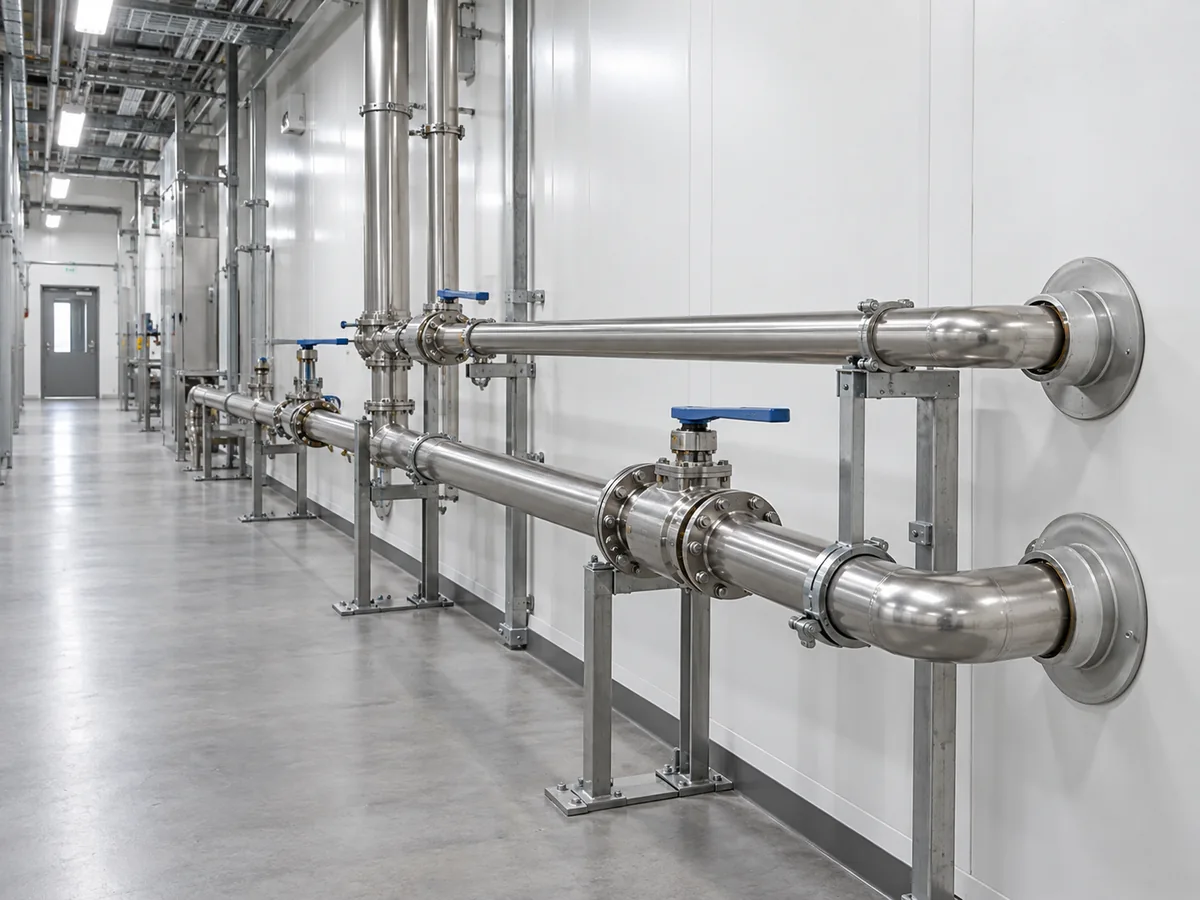
| Space | Planning Focus | Enclosure Interface |
|---|---|---|
| Server hall / white space | Equipment environment, cooling and access. | Partitions, aisle boundaries and service openings. |
| Network and critical equipment rooms | Equipment-specific conditions and maintenance. | Doors, separations and equipment movement. |
| Colocation zones | Tenant boundaries, security and approved routes. | Partitions and access coordinated with fire protection. |
| Disaster-recovery rooms | Defined equipment requirements and readiness procedures. | Room boundaries and service access. |
| Receiving, staging and burn-in areas | Unpacking, cleaning, testing and debris control. | Separation from operating equipment areas. |
| Entry and support spaces | People, tools, materials and cleaning routes. | Entry doors, cleanable surfaces and transfer openings. |
“White space” describes the IT equipment area; it is not an ISO classification. Set any classification target separately.
REPLACE ASSUMPTIONS WITH A ROOM SCHEDULE
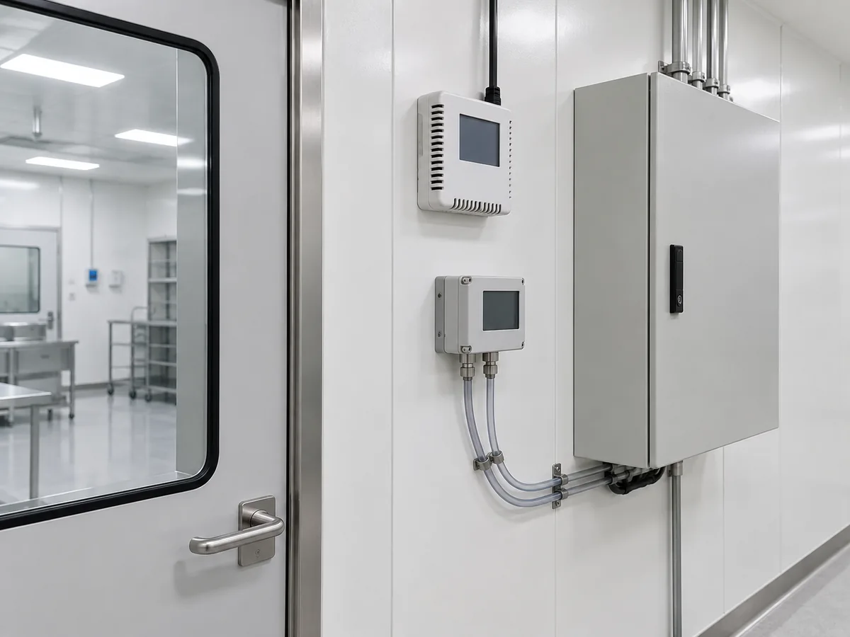
| Requirement | Record in the Brief | Coordinate With |
|---|---|---|
| Temperature & moisture | Equipment inlet conditions, dew point and operating envelope. | Installed equipment documents and cooling designer. |
| Airflow | Supply, return, recirculation and containment paths. | Rack layout and air or liquid cooling package. |
| Particles | Particle sizes, concentration target and testing state, if specified. | Equipment owner and appointed test provider. |
| Filtration | Selected media, pressure drop, fan capacity and change-out access. | Mechanical designer and filter supplier. |
| Pressure relationships | Adjacent spaces, door use and the approved control strategy. | Air balance, fire strategy and enclosure leakage. |
| Corrosive gases | Site risks, assessment method and treatment requirements. | Equipment manufacturer and contamination specialist. |
| ESD & materials | Required surface properties, handling procedures and test method. | Owner’s ESD plan and the complete floor/enclosure assembly. |
There is no single temperature, humidity range, filter grade or air-change rate suitable for every data center. The selected equipment and mechanical design establish the operating requirements.
Equipment example: Dell PowerEdge R260 contamination specifications. Cooling interfaces: NVIDIA DGX GB rack-system guide.
CLASSIFY. MONITOR. TEST.
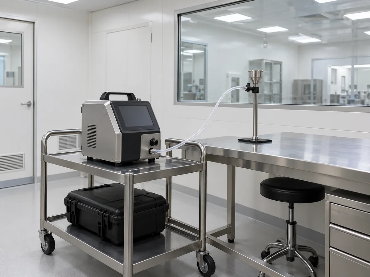
Defines classification of air cleanliness by airborne particle concentration. Agree the class, particle sizes and occupancy state for the specified space.
Official overview →Addresses monitoring that provides evidence of particle-related cleanroom performance. It does not replace routine maintenance of the facility systems.
Official overview →Provides methods for relevant cleanroom performance tests. Select applicable tests and record whether the space is as-built, at-rest or operational.
Official overview →A particle classification report is one part of the evidence package. Cooling acceptance, electrical reliability, fire compliance and product certification have their own requirements.
Technical references reviewed 30 October 2026. Use the editions and acceptance criteria named in the project specification.
CLASSIFICATION / READ THE LIMIT
Compare maximum airborne-particle concentrations at ≥ 0.5 μm. Select a class to highlight its limit; the project brief determines whether a data center needs classification.
| Class | Density* | Limit / Logarithmic Comparison |
|---|---|---|
| ISO Class 5≥ 0.5 μm | 3,520 particles/m³ | |
| ISO Class 6≥ 0.5 μm | 35,200 particles/m³ | |
| ISO Class 7≥ 0.5 μm | 352,000 particles/m³ | |
| ISO Class 8≥ 0.5 μm | 3,520,000 particles/m³ | |
| Particles/m³ · Base-10 Logarithmic Axis | ||
*Particle windows are illustrative, not simulated counts. Classification requires the agreed particle sizes, sampling and occupancy state. ISO classes do not prescribe a universal air-change rate, and EU-GMP grades are not interchangeable class labels. ISO 14644-1 overview · ASHRAE particle-limit table · When does ISO 8 apply?
PARTICLES / GASES / MATERIALS
Airborne particles and corrosive gases need different assessments. Select the treatment path to see why a particulate filter alone does not establish gas-phase protection.
Review outside air and relevant gaseous contaminants, including H₂S and SO₂.
Coordinate filtration, room boundaries and controlled entry with the mechanical designer.
Use the specified measurements and equipment limits to assess the operating environment.
Conceptual educational diagram; not an AILV test result or a service-life prediction. Corrosion depends on materials and exposure conditions. OEM contamination requirements · ASHRAE contamination-control guidance
A MEASURABLE EQUIPMENT REQUIREMENT
Metal-coupon corrosion rates can reveal a gaseous-contamination risk that particle counts do not show. Compare results with the requirements for the installed equipment.
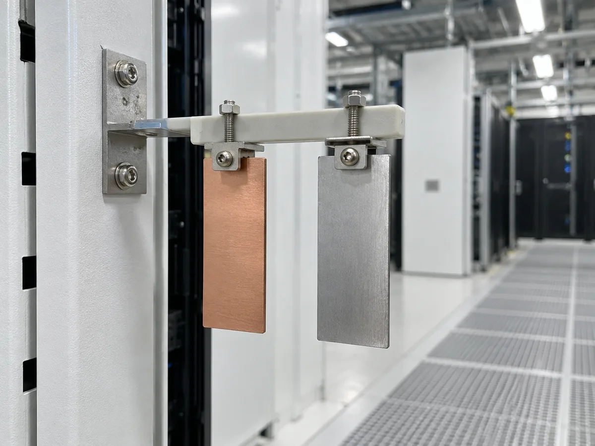
| Reference Metric | Dell PowerEdge R260 Example Limit | Meaning |
|---|---|---|
| Copper corrosion rate | Less than 300 Å/month | The equipment document associates this with ISA71.04 severity level G1. |
| Silver corrosion rate | Less than 200 Å/month | A separate OEM threshold; do not substitute the copper value. |
Å means angstrom. These are equipment-reference corrosion limits, not AILV panel test results or a universal room specification. Agree the monitoring location, exposure conditions and response plan with the appointed specialist.
Sources: Dell R260 contamination requirements · ASHRAE Handbook: data centers and telecommunication facilities.
READ THE FILTER SPECIFICATION
When a design specifies high-efficiency filtration, compare the grade, test conditions and installed system together.
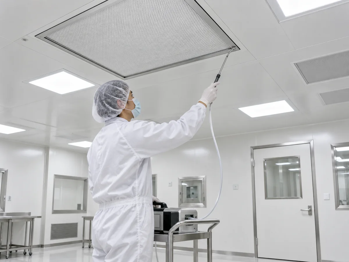
| Filter Class | Group | Minimum Overall Efficiency |
|---|---|---|
| H13 | HEPA | 99.95% at MPPS |
| H14 | HEPA | 99.995% at MPPS |
| U15 | ULPA | 99.9995% at MPPS |
A filter grade describes the filter, while an ISO class describes measured room air. The selected arrangement also needs suitable airflow, pressure-drop allowance, seals and maintenance access. Gas-phase treatment is a separate selection.
Reference: MANN+HUMMEL EN 1822 classification table. This table is a selection reference, not an AILV filter test report or a requirement for every data center.
EXPLORE THE INTERFACES
Select a layout to see where panels, openings and services need coordination. These simplified concepts explain interfaces; your appointed design team defines the cooling system and project details.
Keep supply air and server exhaust paths separate in the approved layout. Containment may use a hot- or cold-aisle arrangement; this concept highlights one supply aisle.
Panel infill, door openings and perimeter interfaces with the selected containment system. The mechanical designer determines airflow and filtration.
Coordinate CDU position, pipe routes, penetrations, leak-detection access and service clearances. Some equipment components can continue to need air cooling.
Related guide: Data Center Panel Pipe-Opening Checklist.
Enclosure openings, access doors and wall or ceiling interfaces around the approved equipment package. Specialist cooling systems remain within their agreed supplier scope.
Agree wall and ceiling locations, door clear openings, vision panels and service penetrations before manufacture. Detail junctions against the approved project requirements.
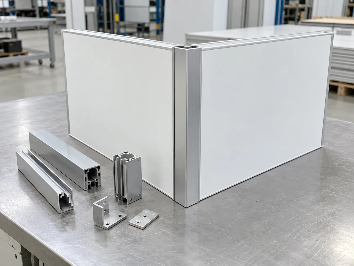
Modular panels, profiles, doors, windows and documented enclosure details. Fire protection, air-tightness and testing criteria require project-specific coordination.
A cooling layout does not determine an ISO cleanliness class. Check the installed equipment requirements and the project contamination-control plan.
ONE AGREED SUPPLY BOUNDARY
Assign each package before ordering, with drawings and documentation linked to the selected products.
| AILV Manufactures | Project Coordination | Appointed Specialists |
|---|---|---|
Handmade and machine-made wall and ceiling panels. Agreed doors, vision windows, profiles and enclosure components. | Panel layout, openings, junctions and installation sequence. Sales and engineering support through K-STONE, with packing and delivery aligned to scope. | HVAC, aisle containment, liquid cooling, electrical and fire-protection systems. Environmental assessment, testing and operating acceptance. |
CHOOSE THE INSTALLATION CONTEXT
Select the project context to see what changes in the enclosure plan.
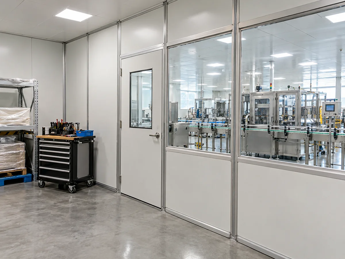
An operating-site programme is agreed with the owner and responsible contractors. Panel prefabrication can reduce site fabrication; it does not by itself guarantee work without an outage.
FROM BRIEF TO PANEL PACKAGE
Expand each input to see what the enclosure team needs.

Room dimensions, elevations, boundaries and installation sequence establish the panel layout and supply quantities.
Rack positions, clearances and equipment entry sizes define access openings and usable working space.
Approved hot- or cold-aisle boundaries identify infill panels, doors and interfaces with the containment supplier.
Supply, return, filter and pressure-control arrangements identify openings and interfaces that affect the room boundary.
CDU positions, pipe penetrations, leak-detection zones and maintenance clearances are coordinated with the cooling supplier.
Cable trays, busways and access requirements identify penetrations, support coordination and installation sequencing.
Fire strategy, compartment lines, suppression and detection layouts define safety interfaces and the documentation schedule.
Loading limits, lifting routes, storage areas and operating-site restrictions inform packing and staged installation.
MATERIAL & DETAILING

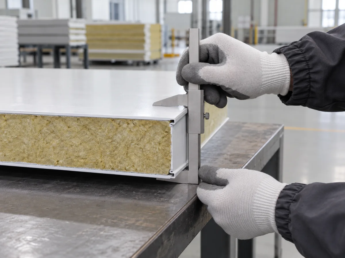
Rock-wool panel sample. Confirm the offered facing, core, edge and joint configuration.
Start with panel dimensions, wall or ceiling use, supports, required fire documentation and surface exposure. Then match a documented configuration to the project. Panel thickness alone does not establish structural capacity, fire performance or room cleanliness.
Panels work together with joints, door seals, service penetrations and floor or ceiling junctions. Agree the sealing details and any leakage-test requirement against the complete assembly and operating conditions.
Request the proposed configuration, layout assumptions, supply exclusions, relevant report references and packing information. Use the AILV report library to review available evidence and its tested construction.
MANUFACTURING & INTERFACE REFERENCES

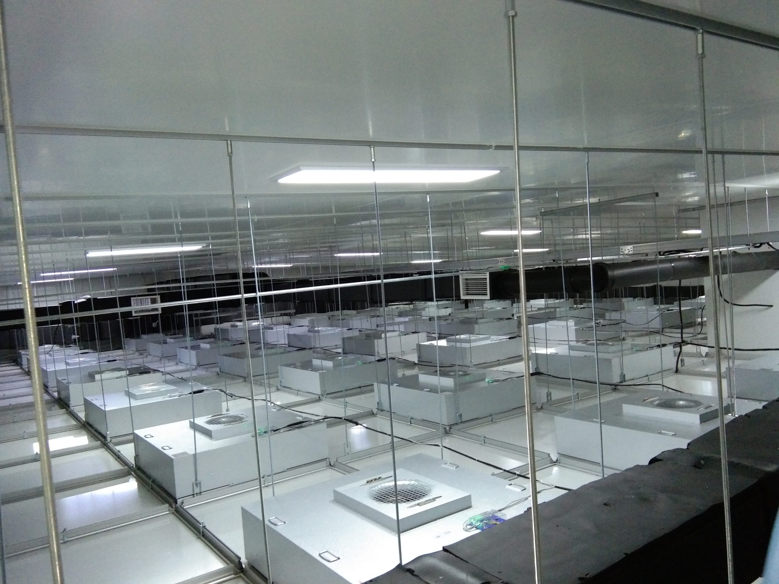
FROM REQUIREMENTS TO A TRACEABLE PACKAGE

AILV’s manufacturing package and K-STONE’s sales and engineering support are defined separately from specialist cooling, electrical, fire and environmental-testing services.
EVIDENCE FOR THE TEAM THAT OPERATES THE ROOM
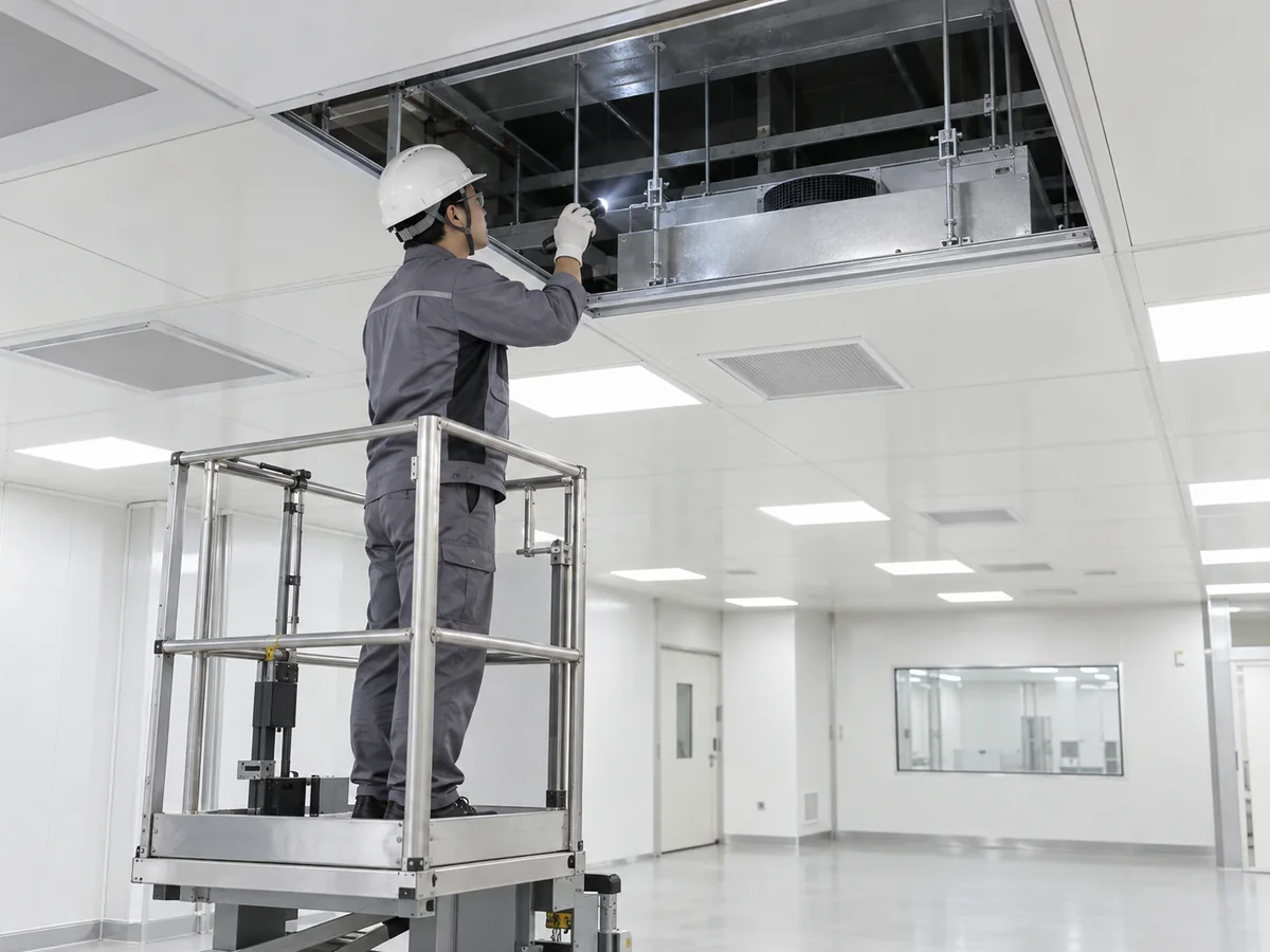
Plan inspections around filter condition, door seals, service changes and cleaning access. Include subfloor spaces where used. The owner’s operating plan defines cleaning methods, monitoring locations, review intervals and responses to out-of-range conditions.
Particle counts cannot establish gaseous corrosivity. Where a site assessment identifies a risk, the equipment and contamination specialists define a suitable monitoring method and treatment review.
They are not a universal requirement for server rooms. Use the owner’s commissioning and acceptance framework; include any qualification documentation expressly required by the project.
References: particle-performance monitoring · data center systems and air-management guidance.
MORE DESIGN QUESTIONS
No. An airborne-particle class is not an air-change prescription. The design considers equipment cooling, contamination sources, filtration, airflow and the specified particle result together.
No. Air distribution can use different arrangements, including overhead delivery. Coordinate the selected supply and return strategy with rack positions, containment and cable routes.
No. Review capture requirements together with pressure drop, fan capability, loading and maintenance. A suitable filter and air-management design should meet the equipment requirements without unnecessary resistance.
The enclosure can be coordinated with the selected air system. Outside-air contaminants, moisture and filter requirements need a site-specific assessment before the openings and control strategy are fixed.
No. Contamination control addresses identified environmental risks. Equipment reliability, operational availability and energy performance depend on the full facility and its operating conditions; evaluate them with project measurements.
For a data center enclosure quotation, send the rack layout, room dimensions, cooling and containment drawings, service openings and equipment-access clearances. Identify new-build or operating-site constraints and separate the panel package from specialist cooling, power, fire-safety and monitoring systems.
COMMON PROJECT QUESTIONS
No. Some equipment specifications call for an ISO Class 8 particulate environment for defined installations. Confirm the equipment, space, testing state and acceptance method. ISO 14644-1 classifies airborne particles; it does not establish cooling or fire requirements. Read the ISO 8 FAQ.
No. Liquid-cooled racks can still contain air-cooled components. Coordinate residual air cooling, CDU access, pipe penetrations and service routes with the equipment and cooling suppliers.
No. Filter selection follows the contamination sources, equipment requirements and mechanical design, including pressure drop, fan capacity and maintenance access. Avoid assigning a universal filter grade or air-change rate.
Yes, where the owner approves the scope and live-site procedures. Review equipment access, temporary separation, debris control, service isolation and installation stages before fixing the enclosure design.
Choose each optional purpose separately. Both start off unless you previously allowed that purpose. Your inquiry works either way.
Your name, email, phone number, message and drawings are not sent by these measurement tags. Privacy Policy