Cleanroom enclosure components
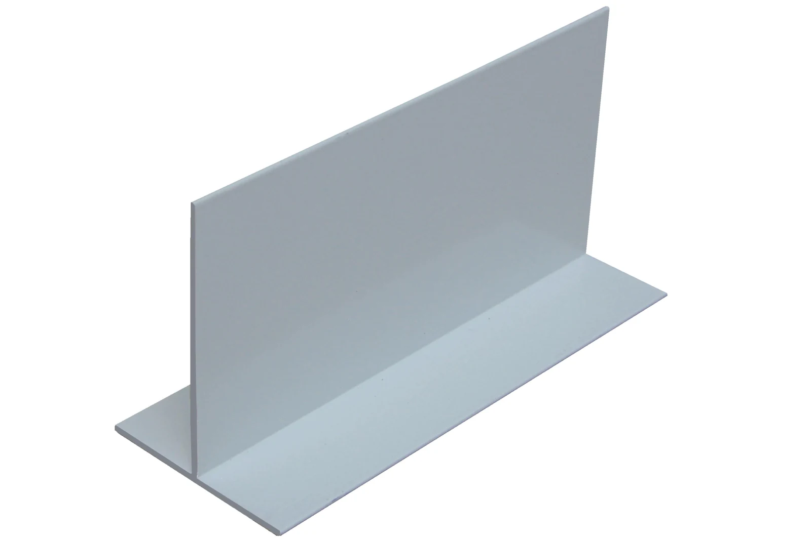
Aluminum profiles connect, locate and finish the edges of a cleanroom enclosure. Choose each profile around the panel section, floor finish, ceiling support and opening detail—not from appearance alone.
Explore central connectors, base tracks, coving and perimeter interfaces alongside AILV wall panels, ceilings, doors and windows.
Start with the panel connection
The connection is different for handmade and machine-made panels. Keep the selected panel section and its matching accessories together on the approved drawing.
Central aluminum connector
The existing AILV straight-joint drawing shows two 50 mm wall panels with a hollow central aluminum connector. The hollow central section locates both panel edges at the joint.
Match the connector to the actual panel-edge recess, insertion depth, joint position and seal arrangement. The 50 mm source detail describes this illustrated assembly; it does not define every available panel or connector.
Open the original junction references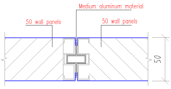
Direct mating of formed panel edges
Machine-made panels connect through their formed male and female edges. A separate central aluminum connector is not required between these panels.
Base tracks, corner trims or opening accessories may still be specified elsewhere in the enclosure. Confirm those perimeter details separately from the panel-to-panel joint.
View machine-made panels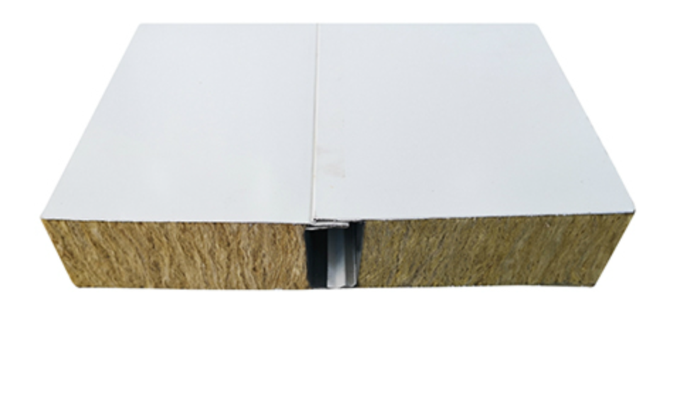
Profile families and where they are used
Use these shapes to begin the selection. The final section, finish, cutting schedule and fixing method belong on the project-specific profile list.
U / base tracks
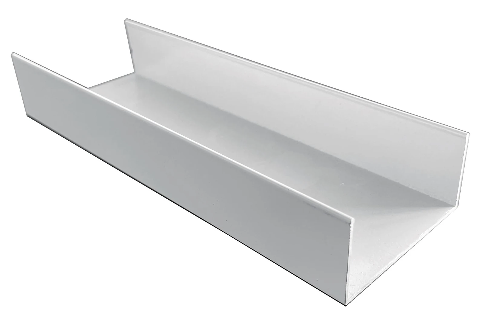
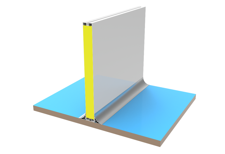
Locate the wall base and coordinate fixings, floor buildup, sealant and the cleanable floor-to-wall junction. Decide whether the floor finish turns up to the wall or a separate coved trim is used.
Internal coving
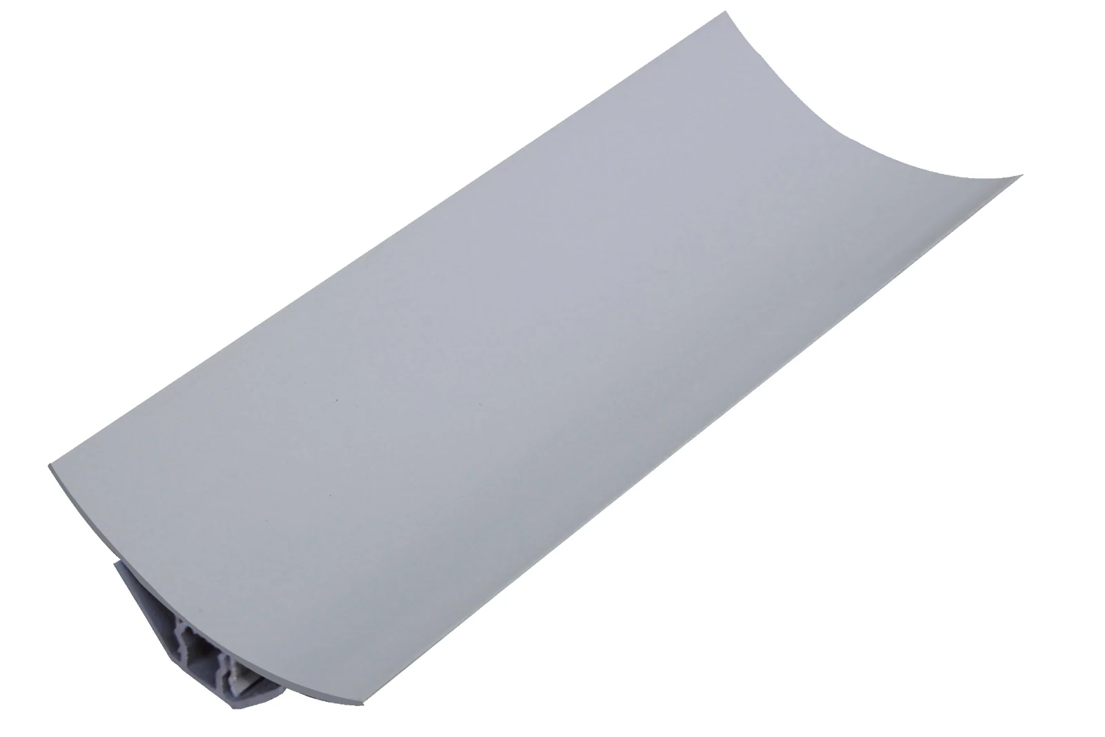
Form a curved transition at an internal junction. Agree the actual curve, backing, end pieces and seal continuity with the adjacent wall and floor finishes.
External corners
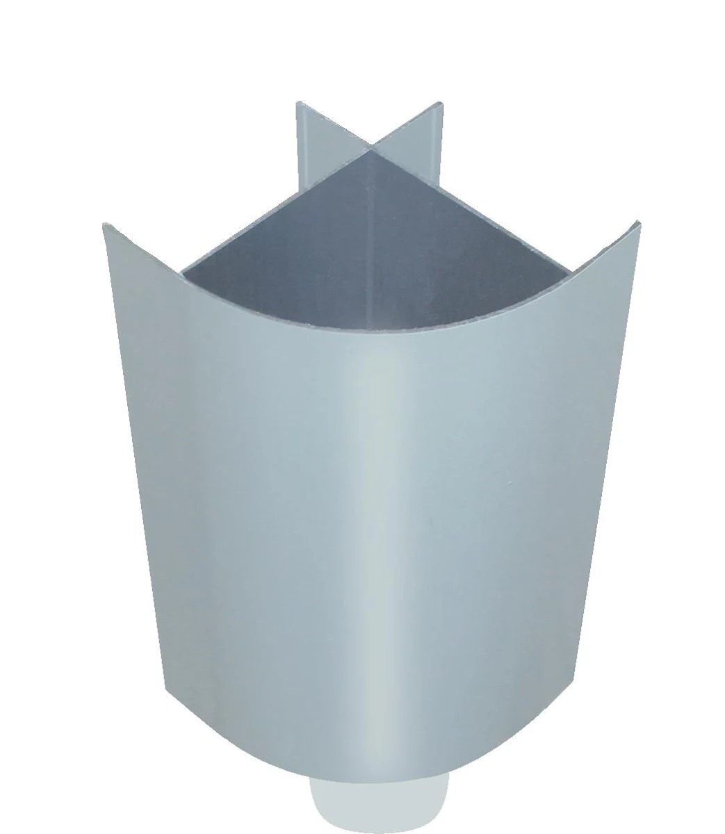
Finish an exposed corner or intersecting panel edges. Coordinate the corner geometry, panel-face alignment and any movement or cleaning requirements.
| Interface | Selection focus | Information to include |
|---|---|---|
| Handmade straight joint | Matched central connecting profile | Panel thickness, edge recess, connector section and seal line |
| Machine-made straight joint | Directly interlocking formed edges | Offered panel-edge drawing; no separate central aluminum connector |
| Wall base / coving | Track, curved finish and floor interface | Floor level, buildup, fixing location, end pieces and sealing |
| Internal / external corner | Corner section and exposed finish | Angle, panel alignment, return dimensions and corner continuity |
| Ceiling connection | Beam/profile with the designed support system | Support layout, panel span, openings and project load requirements |
| Door / window perimeter | Matched frame and panel-edge interface | Opening schedule, frame section, panel thickness and seal location |
Ceiling profiles belong to the support detail
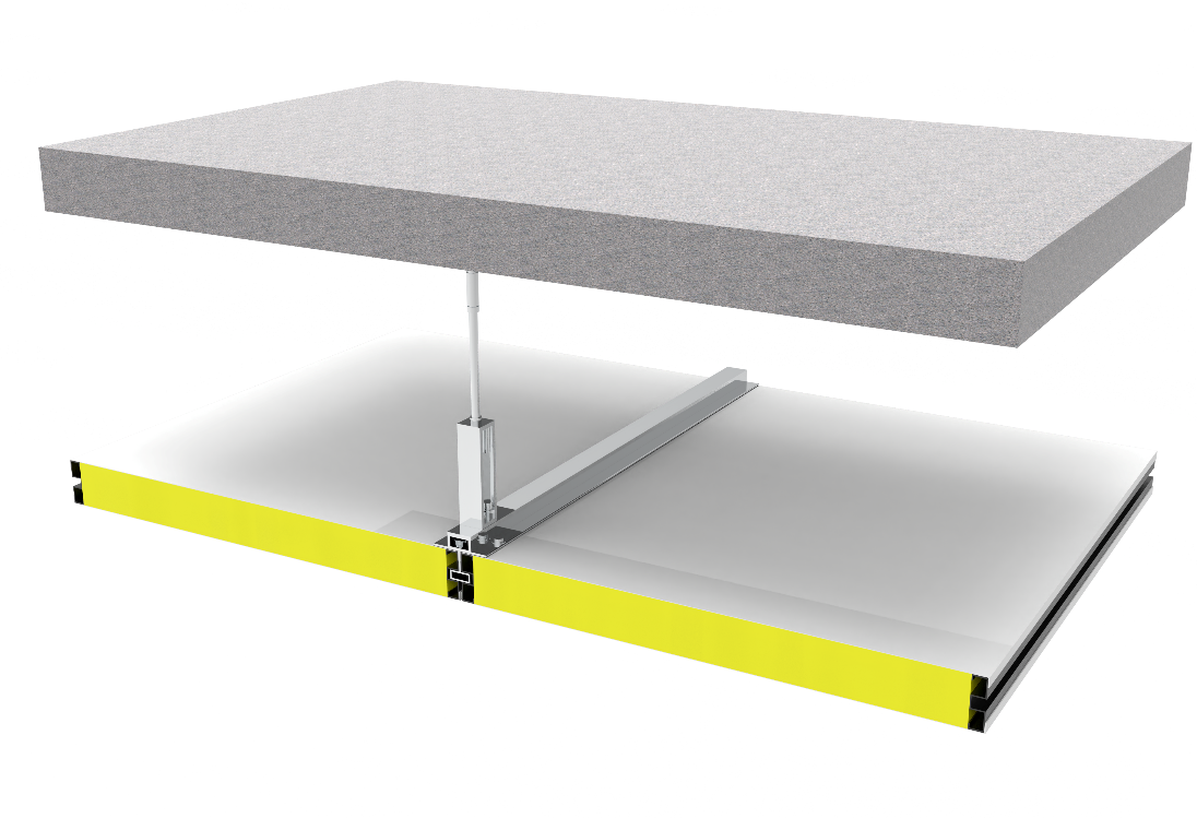
The junction library includes suspended-ceiling beam connections and interfaces around service openings. Select the beam/profile together with the hanger layout, panel connection and the supporting structure.
A profile photo or panel thickness does not establish a walkable ceiling rating. Maintenance access, concentrated loads, equipment openings and allowable deflection require the selected assembly and project support conditions to be checked.
Review ceiling panels and suspension interfacesCoordinate doors and windows at the perimeter
Use the door or window supplier’s frame section alongside the panel detail. The existing AILV junction references show these opening interfaces; they do not mean that every frame uses one universal aluminum profile.
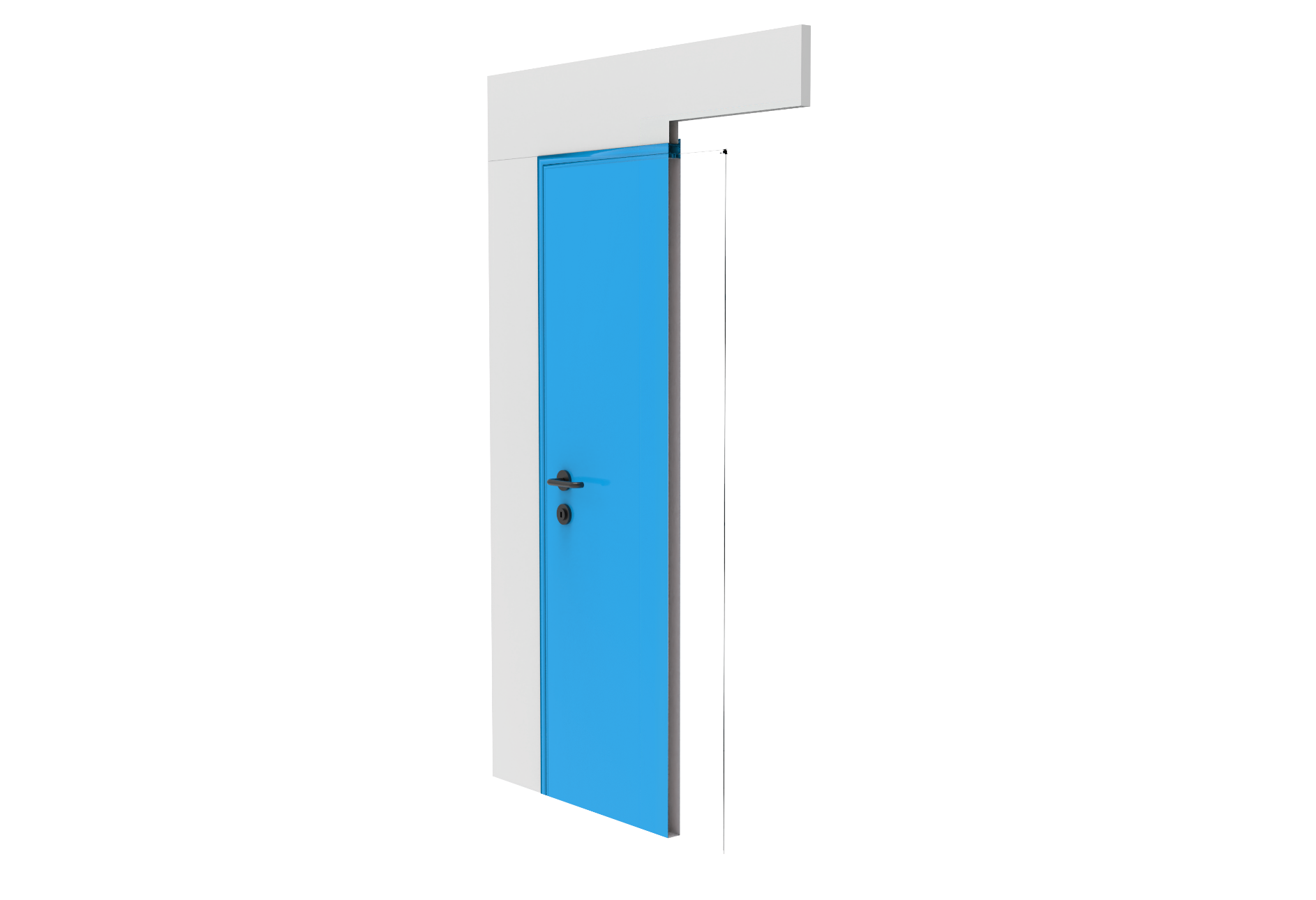
Door-frame interfaces
Confirm the clear opening, frame depth, adjacent panel thickness, fixing position and sealing line. Keep hardware clearance and the required opening function in the door schedule.
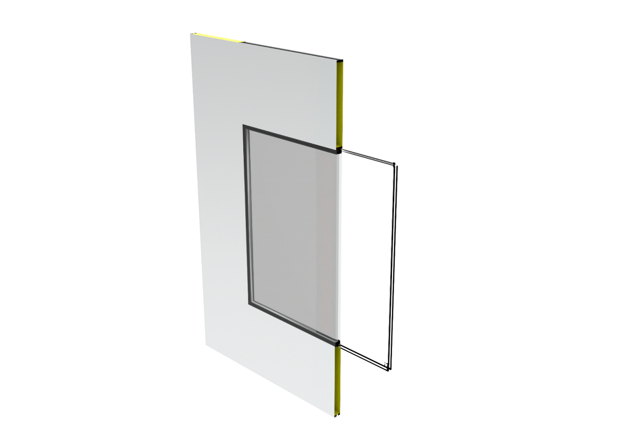
Window-perimeter interfaces
Coordinate the finished opening, frame/rebate arrangement and panel-face alignment. Confirm glazing and perimeter components from the selected window assembly.
Confirm the section before ordering
Send a marked-up plan and the relevant junction sections. A photograph helps identify a shape; a dimensioned section establishes what must fit.
- Panel system: handmade or machine-made, thickness and actual edge section.
- Junction schedule: straight joints, bases, corners, ceilings and opening perimeters.
- Profile details: section drawing, material/finish requirements, lengths, quantities and cutting or drilling needs.
- Interfaces: finished floor levels, wall heights, ceiling supports, door/window schedule and sealant requirements.
- Project conditions: location, applicable specifications, cleaning exposure and the documents needed for approval.
Check material documentation and assembly requirements separately. Panel fire reports or ceiling load reports do not automatically certify an aluminum trim or a different assembled junction.
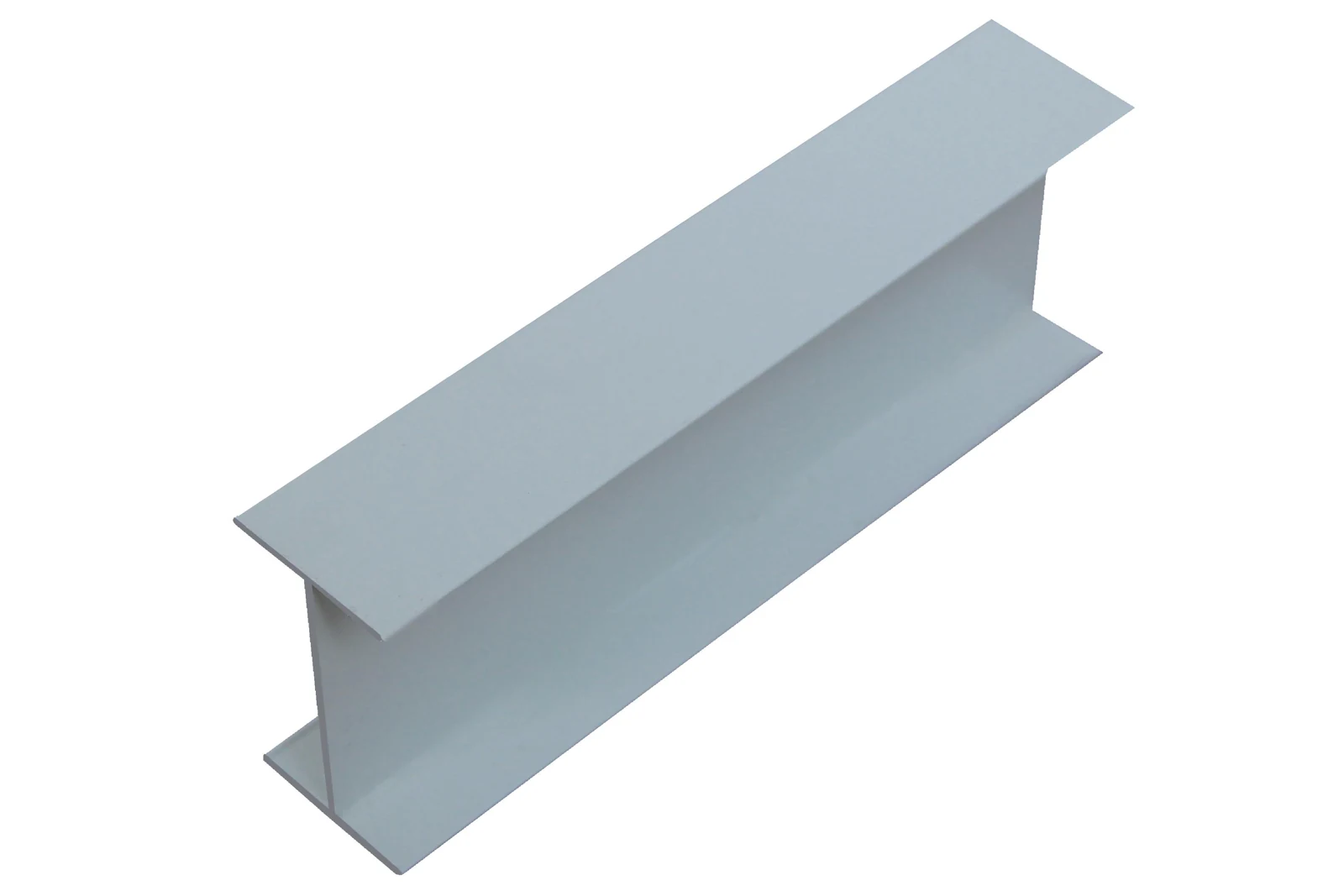
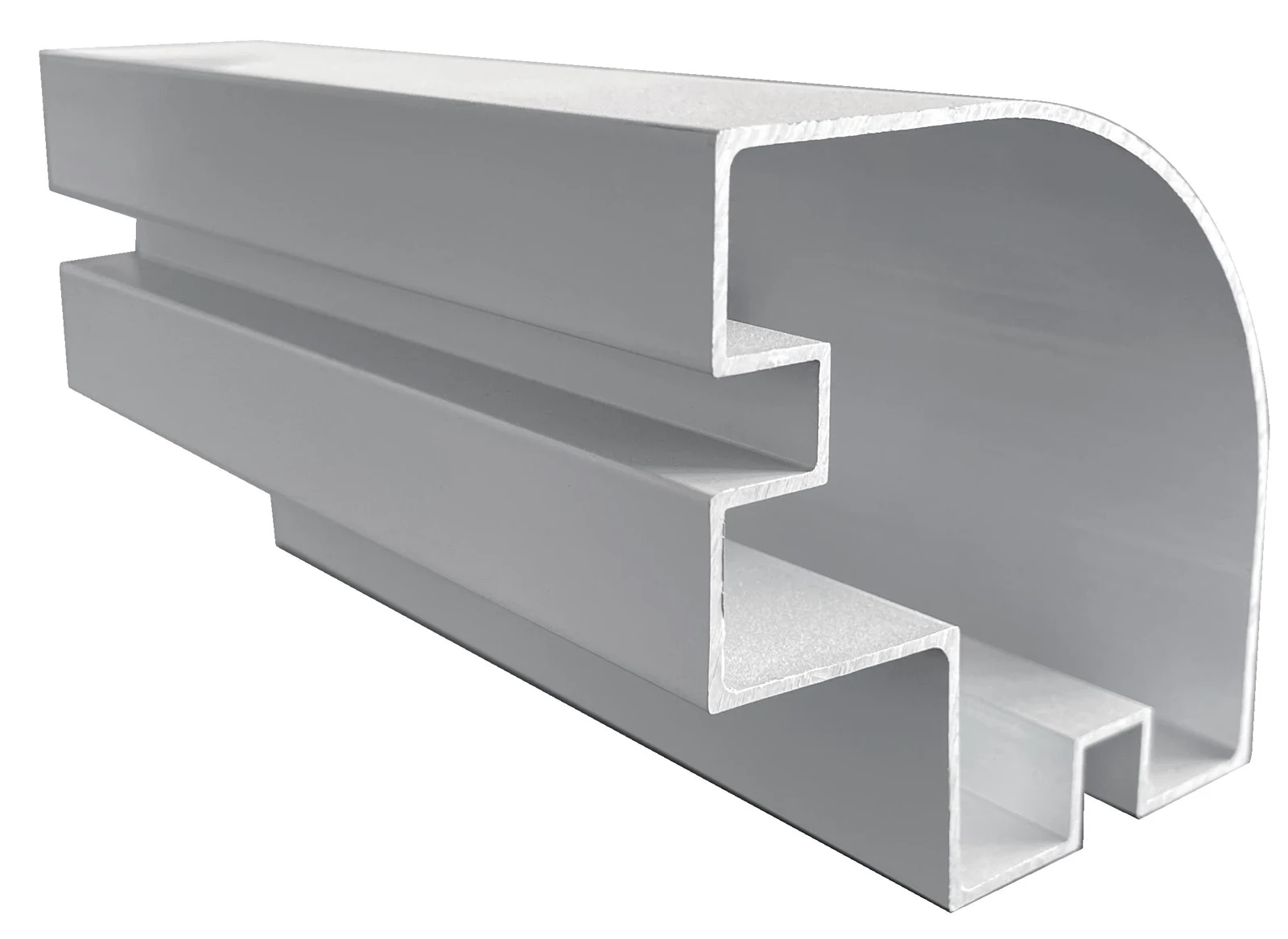
Review the related enclosure details
Use the existing AILV references to identify a junction, then include that reference with your actual panel and opening drawings. AILV’s product team can review the requested enclosure components; the project designer and specialist suppliers remain responsible for their agreed design and performance scope.
Provide the selected profile drawing, quantity and finish requirements with your inquiry. Availability, supplied scope and supporting documents are confirmed for the quoted configuration.
Featured Cleanroom Panels
Explore selected wall and ceiling panel options, or browse the full cleanroom panel range.

50mm Paper Honeycomb Cleanroom Panel | Handmade Cleanroom Panel
AILV 50mm Paper Honeycomb Cleanroom Panel for modular cleanroom wall and ceiling systems. Project-specific ...

50mm Double Magnesium & Aluminum Honeycomb Panel | Handmade Cleanroom Panel
AILV 50mm Double Magnesium & Aluminum Honeycomb Panel for modular cleanroom wall and ceiling systems. Proje...

50mm Double Gypsum & Rockwool Panel | Handmade Cleanroom Panel
AILV 50mm Double Gypsum & Rockwool Panel for modular cleanroom wall and ceiling systems. Project-specific s...

AILV BioGuard Antimicrobial Cleanroom Wall Panel
AILV BioGuard antimicrobial cleanroom wall panels combine a smooth, easy-clean metal surface with an antimi...
Frequently asked questions
Do handmade and machine-made panels use the same central connector?
No. The illustrated handmade straight-joint detail uses a hollow central aluminum connector. Machine-made panels mate through their own formed male and female edges without a separate central aluminum connector. Select the actual model’s edge detail.
Does the 50 mm drawing define every available profile?
No. It documents the illustrated 50 mm wall-panel connection. Confirm the required panel thickness, edge geometry and matching profile section on the project drawings.
What should be confirmed for coving and base tracks?
Confirm the panel and floor interfaces, finished levels, profile section, backing or fixing method, end/corner pieces and seal continuity. The U-channel, curved trim and floor finish must be coordinated.
Can a ceiling profile be specified from a photograph alone?
No. Coordinate the selected profile and support system with panel spans, hanger positions, openings and the project’s access and load conditions. The photo or source junction illustration does not establish a load rating.
Are door and window perimeter profiles universal?
No. Coordinate the actual frame and panel-edge sections, clear openings, finished alignment, fixing method and seals. Use the selected door/window assembly documents.
What information is needed for a profile quotation?
Please send the panel type and section, junction drawings, profile section or sample reference, finish requirements, lengths and quantities, project location and required approval documents. Use the existing Contact inquiry form to discuss the scope.